
In the world of high-volume injection molding, perfection is the goal, and consistency is king. Your process is dialed in, your cycle times are optimized, and production is running smoothly. Then, you see it: a newly ejected part marred by a subtle but critical surface flaw. It’s a frustrating moment that can quickly escalate into a costly problem, leading to increased scrap rates, customer rejections, and production downtime.
Surface defects that appear during or after ejection are particularly insidious. They indicate a fundamental conflict at the most critical moment of the molding cycle: the separation of the finished part from the tool. While operators may be tempted to simply increase the spray of a conventional release agent, this is often a temporary fix that can lead to other problems, such as contamination and mold buildup.
A true solution requires a deeper understanding of the root causes. These defects are rarely the result of a single issue, but rather an imbalance in the complex relationship between process parameters, mold condition, and material science.
This comprehensive guide will help you diagnose and solve five of the most common ejection-related surface defects in injection molding. We will explore the “why” behind each flaw and provide a systematic troubleshooting framework, illustrating how optimizing the interface between the part and the mold—often with an advanced release agent system—is a critical component of the solution.
The Golden Triangle of Troubleshooting: Process, Mold, and Interface
Before diving into specific defects, it’s essential to adopt a holistic troubleshooting approach. Nearly every issue can be traced back to one or more corners of this “Golden Triangle”:
- Process Parameters: These are the dynamic variables you control, including melt and mold temperatures, injection pressure and speed, holding time, and cooling time. An imbalance here is often the first place to look.
- Mold Design & Condition: This includes the physical aspects of the tool itself—draft angles, surface polish (SPI finish), gating, venting, and the condition of the ejector system. A poorly designed or maintained mold will fight you every step of the way.
- The Material & Interface: This encompasses the polymer being used, its preparation (e.g., drying), and, critically, the interface layer between the molten plastic and the steel mold. This interface is controlled by one of the most underestimated components in the entire process: the mold release agent.
Defect #1: Mold Sticking (Part Adhesion)
The most basic ejection failure occurs when the part fails to release from the mold cavity or core. The mold sticking defect causes parts to break or deform or damages the mold tools during ejection.
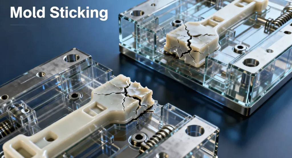
- What It Looks Like: The parts experience cracking or breaking or severe deformation when they exit the mold. The part remains fully enclosed within the mold half when the ejection process fails.
- Common Causes:
- Process: The part remains too soft because of insufficient cooling time which makes it unable to withstand ejection forces. The combination of high melt and mold temperatures leads to chemical bonding and mechanical bonding between the plastic and the mold. The material enters tiny mold surface undercuts because of excessive packing pressure.
- Mold: The main reason for mold sticking occurs when draft angles remain insufficient. The mold surface becomes stuck to the part because of its rough texture or damaged areas that create mechanical bonds. True undercuts exist in the mold design.
Interface: The absence of a release agent or its depletion or selection of an inappropriate agent leads to this issue. The natural lubricating properties of polymers fail to counteract the vacuum forces and mechanical stresses which maintain the part in its position.
- Solutions:
- Review Process Parameters: Begin by increasing cooling time to ensure the part is rigid enough for ejection. Systematically lower the melt temperature and mold temperature in small increments to reduce adhesion without causing other defects like short shots. Finally, reduce packing pressure to the minimum required to prevent sink marks.
- Inspect and Maintain the Mold: Verify that the draft angles in the sticking area are sufficient for the material and texture (a standard rule of thumb is 1-2 degrees per side for polished surfaces, and more for textured ones). Inspect the mold surface for any signs of wear, erosion, or scratches and repolish if necessary.
- Optimize Your Release Agent System: This is the most direct way to modify the mold-part interface. If you are not using a release agent, applying one is the first logical step. If you are, it may be the wrong type. A semi-permanent release agent can be a powerful solution. Unlike sacrificial agents that transfer to the part and must be reapplied frequently, a semi-permanent system creates a durable, micro-thin polymer layer bonded to the mold. This provides consistent release over many cycles and eliminates the variables of manual application.
Defect #2: Drag Marks or Scuffing
The surface of molded parts develops parallel lines which appear as scratches or drag marks that follow the ejection direction. The part surface experiences high-friction contact with the mold during separation which results in drag marks.
- What It Looks Like: The surface shows parallel lines that appear as fine or deep marks that sometimes display melted or glossy areas compared to the surrounding surface.
- Common Causes:
- Process: The ejection process creates excessive friction, which leads to surface heating of the part. The mold receives excessive packing pressure which causes the material to touch the mold walls with increased force.
- Mold: The main reason for this defect stems from insufficient draft angles in the mold design. The draft requirements for textured surfaces exceed the requirements needed for polished surfaces. The ejector pins will create damage to the part through their contact points when they encounter any small mold undercuts or sharp edges.
- Interface: The surface of the material lacks sufficient lubrication properties. The plastic material shows excessive friction with steel materials during contact. The release agent helps with part separation, but it lacks sufficient lubrication properties to enable part movement.
- Solutions:
- Adjust Ejection Profile: The ejector pins need to start their ejection process at a low speed before they achieve their highest speed. Modern molding machines enable operators to perform multi-stage ejection through which they can start with gentle ejection before increasing speed.
- Optimize Packing Pressure: The packing pressure needs to be reduced to its lowest possible setting which stops sink or void formation. The mold wall normal force decreases when you lower the packing pressure which results in reduced friction.
- Enhance Surface Slip with the Right Release Agent: This is a classic interface problem. You need a release agent that provides high levels of “slip.” Look for formulations based on PTFE or other specialized fluoropolymers. These create an extremely low-friction surface, allowing the part to glide out of the mold smoothly rather than being dragged out. This is another area where a stable, bonded semi-permanent coating excels over an inconsistent, oily sacrificial layer.
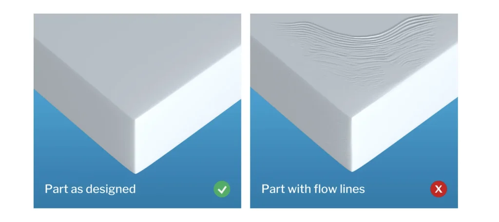
Defect #3: Inconsistent Gloss or Surface Finish
Molded parts develop uneven gloss patterns on their surface which results in unattractive visual imperfections. The plastic material fails to replicate the mold surface correctly which results in this defect.
- What It Looks Like: The part surface shows different gloss levels between dull and shiny areas which appear as swirls or patches or distinct dark spots.
- Common Causes:
- Process: The process produces irregular melt temperature values and flow front velocity measurements. The mold surface experiences different cooling rates which lead to temperature differences. The presence of water in plastic materials leads to surface finish problems during processing.
- Mold: The mold surface presents irregularities between its polished and textured areas. The mold face temperature becomes uneven because of poor cooling channel design.
- Interface: The release agent application becomes uneven because of improper release agent distribution or excessive buildup. The method of release agent application results in surface gloss variations because areas with heavy application thickness produce different gloss levels than areas with light application thickness. The release agent residue that accumulates on mold surfaces leads to surface texture changes.
- Solutions:
- Stabilize the Process: The material drying process needs to follow manufacturer guidelines for proper drying. The heater bands should maintain stable temperatures while the melt temperature needs to stay constant. The injection speed needs to follow a smooth path to achieve uniform filling.
- Mold surface inspection should begin with a thorough cleaning process. The recommended cleaning solution should be used to remove all residue and buildup from the mold surface. The surface quality and polish level of the mold need verification. The pyrometer should measure mold surface temperatures across different areas to detect hot and cold spots.
- A high-integrity release system should be implemented to solve gloss variation problems. A perfectly uniform micro-thin layer becomes impossible to achieve through manual aerosol application methods. The application of wipe-on or spray-automated semi-permanent release agents creates a uniform non-transferring film which stops buildup while maintaining the original surface quality of parts. The release agent protects the original mold finish through every production cycle.
Defect #4: Blisters or Bubbles
Blisters appear as raised hollow bumps which form on the surface of molded parts. The plastic surface layer contains trapped gas which expands into blisters when the part exits the mold under external pressure reduction.
- What It Looks Like: The part surface shows smooth raised bumps which resemble small to large bubbles.
- Common Causes:
- Process: The combination of high processing temperatures with excessive heat causes polymer degradation which produces gas. The part surface becomes too weak to contain internal gas pressure because of insufficient cooling time.
- Mold: The mold lacks sufficient venting channels which allows gases to become trapped inside the part.
- Interface/Material: The mixture of plastic pellets with water produces steam which creates bubbles through the process. The release agent fails to perform its function when it cannot withstand processing temperatures because it either vaporizes or burns off to create trapped gases inside the part.
- Solutions:
- Control your materials and temperature. The material drying process should follow manufacturer guidelines while avoiding over-drying because it creates additional problems. The barrel and nozzle temperatures should be decreased step by step to stop material degradation.
- Improve the mold venting. The current mold venting system requires enhancement to achieve optimal results. The mold vents require inspection followed by cleaning operations. The tool setup process should avoid damaging or crushing vents because they serve as the first point of failure. The vents need to extend to the point where they release air but should not cross the threshold which produces excessive flash.
- Select a Thermally Stable Release Agent: The release agent needs to stay stable during processing at temperatures which match your production needs. The creation of high-temperature semi-permanent release agents resulted in products which maintain their stability at temperatures exceeding standard molding temperatures. The release agent remains stable throughout processing so the material and air in the cavity remain as the only potential gas sources.
Defect #5: Ejector Pin Marks
The ejector pins create visible marks which include stress marks and punctures and whitening effects on the molded parts. The ejection process requires excessive force to separate the part from the mold.
- What It Looks Like: The part surface shows circular marks which appear as shiny or dull spots and deep indentations and white stress marks.
- Common Causes:
- Process: The part remains too soft because of insufficient cooling time which makes it unable to withstand ejection forces. The part experiences excessive mold pressure during packing which causes it to shrink tightly against the core. The ejection process needs to run at high speeds while using strong forces to perform its designed purpose.
- Mold: The ejector pins do not have sufficient dimensions to cover their designated surface area which results in localized force distribution. The ejector pins fail to reach the mold surface when they retract because of this issue. The part fails to release from the core because the core lacks sufficient draft angles.
- Interface: The material shows excellent friction performance. The part remains stuck to the mold through strong adhesion forces which require strong ejection forces to separate it. The release agent fails to create a smooth separation between the part and mold surface.
- Solutions:
- Optimize Ejection and Cooling: The part requires an extended cooling period to reach proper rigidity before ejection can occur. The ejector force and speed should be minimized to their lowest possible values. The ejection process should use multiple pins which push the part simultaneously.
- Evaluate Mold Design: The evaluation of mold design should incorporate additional ejector pins which have expanded contact areas to distribute ejection forces. All cores and deep ribs require particular draft angles to achieve their intended operation.
- Dramatically Reduce Release Force: The solution to this problem requires a major decrease in release force. The main problem occurs because the parts fail to release properly from their molds. A high-performance release agent will decrease the necessary ejection force to a significant extent. A high-quality semi-permanent release system reduces ejection force requirements by more than 50% which results in fewer pin marks and reduced part stress and expanded processing windows.
Conclusion: From Firefighting to Process Control
Surface defects on molded parts function as warning signs which indicate your production process has reached an unstable state. The solution to most problems requires adjusting temperature and pressure and time settings but these changes do not solve the main issue of high-friction contact between the part and mold.
The modern mold release agent is not a simple lubricant or a crutch for a bad process. It is a piece of precision chemical engineering—a tool that allows you to control that interface. By choosing a high-performance, semi-permanent system tailored to your material and process temperature, you can:
- Drastically reduce the force needed for ejection.
- Create consistent, high-slip surfaces.
- Eliminate contamination and gloss variation.
- Protect your valuable mold from residue buildup and wear.
Instead of fighting defects one by one, a strategic approach to your release system allows you to create a more stable, repeatable, and profitable molding process. The next time you see a flaw on a part, look beyond the machine settings and consider the critical, invisible layer that can make all the difference.